System List
This screen grasps the overall operating status from a list of the status of each unit. When an error unit is detected at this screen, shift to the "Error History" screen, then check the detailed status.
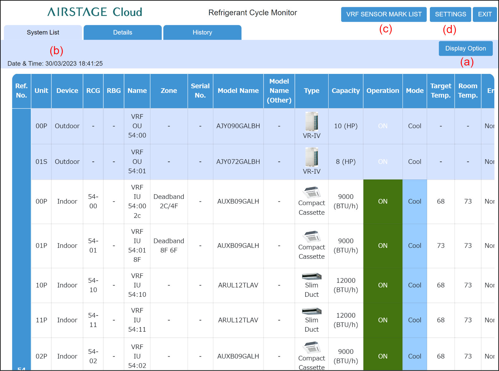
Control area
(a) [Display option] button
Selects display / hidden for the item displayed at list area.
(b) Date & Time
The date and time setting at "Details Diagrams" are displayed.
(c) [VRF SENSOR MARK LIST] button
Shows the item names and contents displayed on the Schematic and Graph screens.
(d) [SETTINGS] button
Displays the Settings screen. The unit of temperature, pressure or capacity can be changed.
List display area
| Ref. No. | Displays the refrigerant system address |
| Unit | Displays the Unit No. and primary/secondary operation for outdoor unit and indoor unit. |
| Device | Displays the Indoor unit or Outdoor unit. |
| RCG | Displays the Remote Controller Group. |
| RBG | Displays the RB Unit Group No. |
| Name | Displays the unit name. |
| Zone | Displays the Zone Name setting for each indoor unit. |
| Serial No. | Displays the Serial No. setting for each outdoor unit and indoor unit. |
| Model Name | Displays the model name of the unit. |
Model Name (Other) |
Displays the model name of the attached unit of the unit. |
| Type | Displays the unit type. |
| Capacity | Displays the indoor unit and outdoor unit capacity. (*1) Indoor unit: Units display is [BTU/h] or [kW]. Outdoor unit: Units display is [HP] or [t(ton)] , [kW]. |
| Operation | Displays the operating status. |
| Mode |
Displays the operating mode. [ |
| Target Temp. | Displays the setting temperature. (*1) Units display is [°C] or [°F]. Dual Setpoint Auto: Set the set temperature for cooling and the set temperature for heating separately. During the Dual Setpoint Auto mode operation, when the room temperature exceeds the set temperature for cooling, the cooling operation is performed, and when the room temperature falls below the set temperature for heating, the heating operation is performed. (It can be used only when the setting of the indoor unit compatible with this function is valid.) |
| Room Temp. | Displays the room temperature. (*1) Units display is [°C] or [°F]. |
| Error | Displays the Error message while an error is occurring for the unit. |
Special Operation icon |
Displays the special operation status using icon. Refer to "List of icon for special operation". |
| Fan | Displays the fan status. (*2) |
Up/down Airflow Direction |
Displays up/down airflow louver position. |
Left/right Airflow Direction |
Displays left/right airflow louver position. |
| RC Prohibition | Displays the RC Prohibition setting. |