Details Status List
The Details Status List screen can be displayed by tapping [STATUS LIST] tab at the Control area.
In this screen, detail data for all the units in the specified refrigerant system will be displayed at a certain point of time.
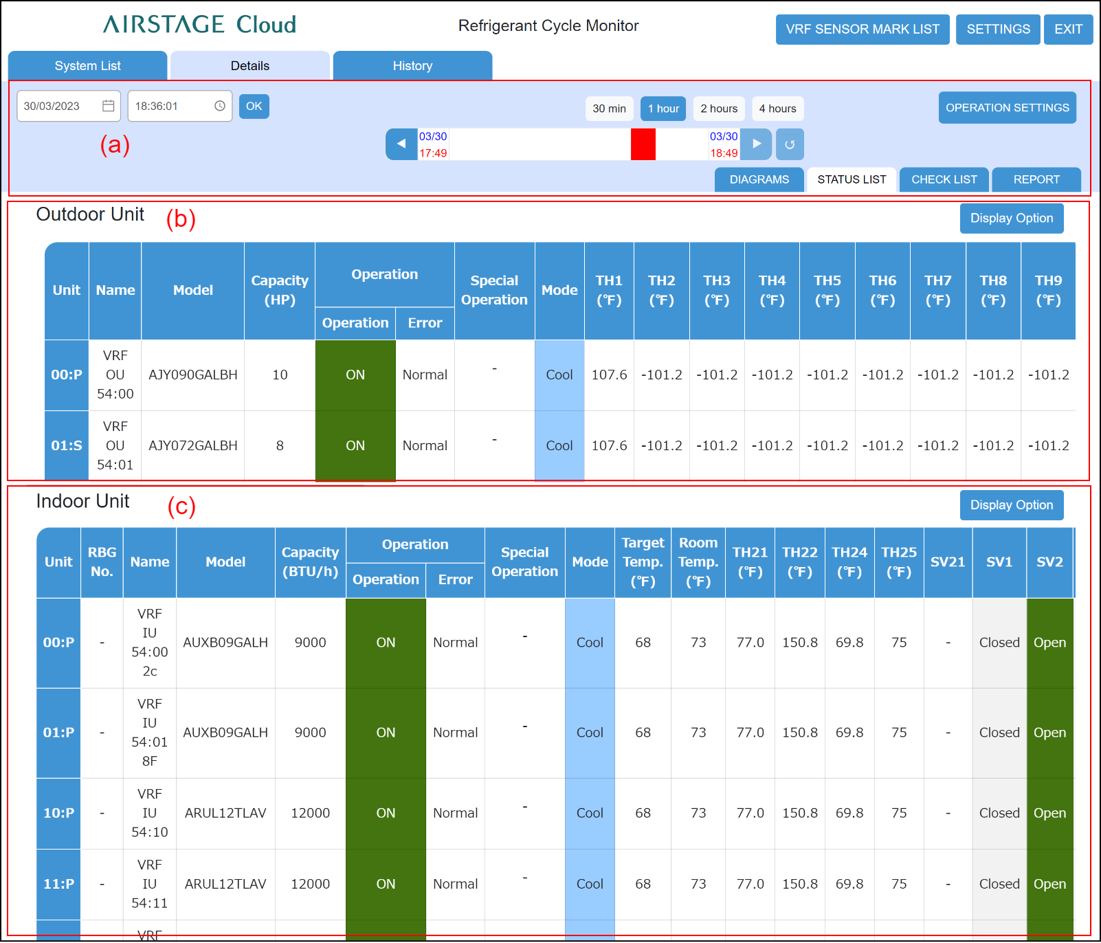
(a) Control area
(b) Outdoor Unit status list area
(c) Indoor Unit status list area

Control area
(a) Date setting field
Sets the date of data you want to display at the Details Status List screen.
(b) Time setting field
Sets the time of data you want to display at the Details Status List screen.
(c) [OK] button
Confirms the date and time set at (a) and (b) and updates the screen.
(d) [![]() ] button
] button
Sets the time displayed on the gauge before the time currently displayed.
(e) 4 hours gauge
Sets the time displayed on the Status List. The time range that can be displayed on the gauge is set by (g) button.
The date and time are set by moving the probe using the drag and drop of mouse.
(f) [![]() ] button
] button
Advances the time displayed on the gauge ahead of the time currently displayed.
(g) [Gauge Time Selection] button
Specifies the X-axis scale (30 min / 1 hour / 2 hours / 4 hours) of the graph.
(h) [![]() ] (Auto Refresh) button
] (Auto Refresh) button
Updates the screen to the latest data.
[![]() ] (Blue): Updates the screen to the latest data automatically.
] (Blue): Updates the screen to the latest data automatically.
[![]() ] (Gray): Does not update the screen automatically.
] (Gray): Does not update the screen automatically.
(i) [Operation settings] button
Operates the indoor units for RC group. Tap the [Send] button after operation.
(j) [DIAGRAMS] tab
Displays the Details Diagrams screen.
(k) [STATUS LIST] tab
Displays the Details Status List screen.
(l) [CHECK LIST] tab
Displays the Details Check List screen.
(m) [REPORT] tab
Displays the Details Report screen.
Outdoor Unit status list area
(n) [Display Option] button
Selects display / hidden for the item displayed at list area.
The Display Option button of the Indoor unit is also the same.
Displays the following operation status of each outdoor unit according to the condition given in the Control area.
| Unit | Displays the unit No. |
|
Name |
Displays the unit name. |
|
Model |
Displays the model name of the unit. |
| Capacity | Displays the capacity of outdoor unit. (*1) Units display is [HP] or [t(ton)] , [kW]. |
| Operation | Displays the operating status (ON/OFF) and unit status (Normal/Error). |
| Special operation icon | Displays the special operation status using icon. Refer to "List of icon for special operation". |
| Mode | Displays the operating mode. |
* For each sensor information, tap the [VRF SENSOR MARK LIST] button.
Indoor Unit status list area
(o) [Display Option] button
Selects display / hidden for the item displayed at list area.
The Display Option button of the Outdoor unit is also the same.
Displays the following operation status of each indoor unit according to the condition given in the Control area.
| Unit | Displays the unit No. |
|
RBG No. |
Displays the RB Unit Group No. |
|
Name |
Displays the unit name. |
| Model | Displays the model name of the unit. |
| Capacity | Displays the capacity of indoor unit. (*1) Units display is [BTU/h] or [kW]. |
| Operation | Displays the operating status (ON/OFF) and unit status (Normal/Error). |
| Special operation icon | Displays the special operation status using icon. Refer to "List of icon for special operation". |
| Mode |
Displays the operating mode. [ |
| Target Temp. | Displays the setting temperature. (*1) Units display is [°C] or [°F]. Custom Auto: Set the set temperature for cooling and the set temperature for heating separately. During the Custom Auto mode operation, when the room temperature exceeds the set temperature for cooling, the cooling operation is performed, and when the room temperature falls below the set temperature for heating, the heating operation is performed. (It can be used only when the setting of the indoor unit compatible with this function is valid.) |
| Room Temp. | Displays the room temperature. (*1) Units display is [°C] or [°F]. |
Up/down Airflow Direction |
Displays up/down airflow louver position. |
Left/right Airflow Direction |
Displays left/right airflow louver position. |
*For each sensor information, tap the [VRF SENSOR MARK LIST] button.