Details Diagrams
The Details Diagrams screen can be displayed by tapping [DIAGRAMS] tab at the Control area.
This screen displays the schematic, sensor values, and electrical components operating status of the selected system. At this screen, normal operation checks, and cause specification when an error occurs are performed.
Schematic or Graph screen of all units connected for refrigerant system can be checked by scrolling the screen.

(a) Control area
(b) Outdoor Unit schematic area
(c) Outdoor Unit graph area
Control area
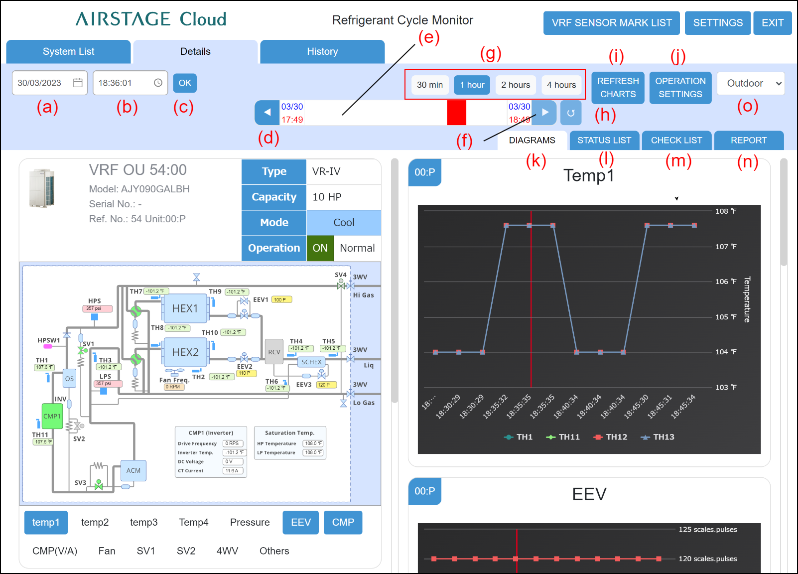
(a) Date setting field
Sets the date of data you want to display at the Schematic screen.
(b) Time setting field
Sets the time of data you want to display at the Schematic screen.
(c) [OK] button
Confirms the date and time set at (a) and (b) and updates the screen.
(d) [![]() ] button
] button
Sets the time displayed on the gauge before the time currently displayed.
(e) 4 hours gauge
Displays or sets the time on the graph screen or schematic screen. The time range that can be displayed on the gauge is set by (g) button.
The date and time are set by moving the probe using the drag and drop of mouse.
(f) [![]() ] button
] button
Advances the time displayed on the gauge ahead of the time currently displayed.
(g) [Gauge Time Selection] button
Specifies the X-axis scale (30 min / 1 hour / 2 hours / 4 hours) of the graph.
(h) [![]() ] (Auto Refresh) button
] (Auto Refresh) button
Updates the screen to the latest data.
[![]() ] (Blue): Updates the screen to the latest data automatically.
] (Blue): Updates the screen to the latest data automatically.
[![]() ] (Gray): Does not update the screen automatically.
] (Gray): Does not update the screen automatically.
(i) [REFRESH CHARTS] button
Displays the chart of graph area in the latest state.
(j) [OPERATION SETTINGS] button
Operates the indoor units for RC group. Tap the [Send] button after operation.
(k) [DIAGRAMS] tab
Displays the Details Diagrams screen.
(l) [STATUS LIST] tab
Displays the Details Status List screen.
(m) [CHECK LIST] tab
Displays the Details Check List screen.
(n) [REPORT] tab
Displays the Details Report screen.
(o) Unit Selection field
Outdoor Unit or Indoor Unit can be selected.
Outdoor Unit schematic and graph area
Displays the schematic of all outdoor units connected to refrigerant system. For the meaning of each symbol, refer to the “Design & Technical Manual”. For the meaning of each item in the schematic, refer to the later “Schematic /Graph display item”.

(a) Schematic
| Schematic | Displays the schematic for outdoor unit. |
|
Compressor |
Displays the compressor status. |
|
4-way valve/solenoid valve |
Displays the 4-way valve/solenoid valve status. |
(b) Display items
| Name | Displays the unit name. (*1) |
| Model | Displays the model name. |
Serial No. |
Displays the Serial No. |
| Ref. No. | Displays the Refrigerant system address. |
| Unit | Displays the unit number. |
Special operation icon |
Displays the special operation status using icon. Refer to "List of icon for special operation". |
| Type | Displays the unit type. |
| Capacity | Displays the capacity of outdoor unit. (*2) Units display is [HP] or [t(ton)], [kW]. |
| Mode | Displays the operating mode. |
| Operation | Displays the operating status (ON/OFF) and unit status (Normal/Error). |
(c) Graph button
The Graph corresponding to the clicked button is displayed.
| Temp.1 | Displays the 4 temperature graphs at the graph area. |
| Temp.2 | |
| Temp.3 | |
| Temp.4 | |
| Pressure | Displays a pressure graph at the graph area. |
| EEV | Displays an electrical expansion valve opening pulse graph at the graph area. |
| CMP | Displays the operating status of the compressor at the graph area. For an inverter compressor, the operation frequency is also displayed. |
| CMP(V/A) | Displays the inverter voltage value and current value of compressor. |
| FAN | Displays the operation status of fan at the graph area. |
| SV1 | Displays the operation status of solenoid valve at the graph area. |
| SV2 | Displays the operation status of solenoid valve at the graph area. |
| 4WV | Displays the operation status of 4-way valve at the graph area. |
| Others | Displays the special operation status at the graph area. |
(d) Graph area
The outdoor unit graph is displayed. Graph figures are displayed by the mouse over on the graph.
Indoor Unit schematic and graph area
Displays the schematic and graph of all indoor units connected to refrigerant system. For the meaning of each item in the schematic, refer to the later "Schematic/graph display item".
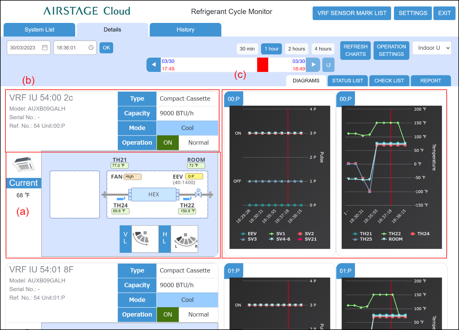
(a) Schematic
| Temp. | Displays the setting temperature. (*2) Units display is [°C] or [°F]. Custom Auto: Set the set temperature for cooling and the set temperature for heating separately. During the Custom Auto mode operation, when the room temperature exceeds the set temperature for cooling, the cooling operation is performed, and when the room temperature falls below the set temperature for heating, the heating operation is performed. (It can be used only when the setting of the indoor unit compatible with this function is valid.) |
| Schematic | Displays the schematic for indoor unit. The RB unit status will only be displayed beside the refrigerant system when the system type is heat recovery. |
| VL | Displays the up/down airflow louver position. |
| HL | Displays the left/right airflow louver position. |
(b) Display items
| Name | Displays the unit name. (*1) |
| Model | Displays the model name. |
Serial No. |
Displays the Serial No. |
| Ref. No. | Displays the Refrigerant system address. |
| Unit | Displays the unit number. |
| Special operation icon | Displays the special operation status using icon. Refer to "List of icon for special operation". |
| Type | Displays the unit type. |
| Capacity | Displays the capacity of indoor unit. (*2) Units display is [BTU/h] or [kW]. |
| Mode |
Displays the operating mode. [ |
| Operation | Displays the operating status (ON/OFF) and unit status (Normal/Error). |
(c) Graph
Graph screen of all indoor units can be checked by scrolling the screen. Schematic and graph are scrolled at the same time.
2 types of graphs are displayed for one indoor unit. Graph screen cannot be added or deleted.
Graph figures are displayed by the mouse over on the graph.
Schematic/graph display item
Shows the item names and contents displayed on the Schematic and Graph screens. The items in the graph button field can be graphically displayed with the graph button of the relevant name.
For the sensor information, tap the [VRF SENSOR MARK LIST] button.
Outdoor unit
J-II, J-IIS, J-III, J-IIIL |
VR-II, V-III |
|
|---|---|---|
| Temp.1 | TH1, TH2, TH10, TH11 |
TH1, TH11, TH12, TH13 |
| Temp.2 | TH3, TH5, TH6, TH7 |
TH7, TH8, TH9, TH10, TH14, TH15 |
| Temp.3 | TH4, TH8, TH9 |
TH2, TH3, TH4, TH5, TH6 |
| Temp.4 | HP, LP |
|
| Pressure | HPS, LPS, HPSW1, HPSW2, MPS (V-III only) | |
| EEV | EEV1, EEV2, EEV3 | |
| CMP | CMP1, CMP2, INV1_FREQ | |
CMP (V/A) |
INV1_VOLT, INV_CURRENT, CNST_CURRENT | |
| FAN | FAN1_FREQ, FAN2_FREQ | |
| SV1 | SV1, SV2 ,SV3, SV4, SV5, SV6 | |
| SV2 | SV7, SV8, SV9 | |
| 4WV | 4WV1, 4WV2, 4WV3 | |
Others |
Oil recovery operation, Defrost operation, Low noise, Capacity save operation, Forced Thermostat Off Operation, Refrigerant leak detection, Maintenance mode, Emergency stop |
|
Indoor unit
J-II, J-IIS, J-III, J-IIIL, VR-II, V-III |
|
|---|---|
| Graph1 | ROOM, TH21, TH22, TH24, TH25 |
| Graph2 | EEV, SV1, SV2, SV3, SV4-6,SV21 |