


 Europe | English
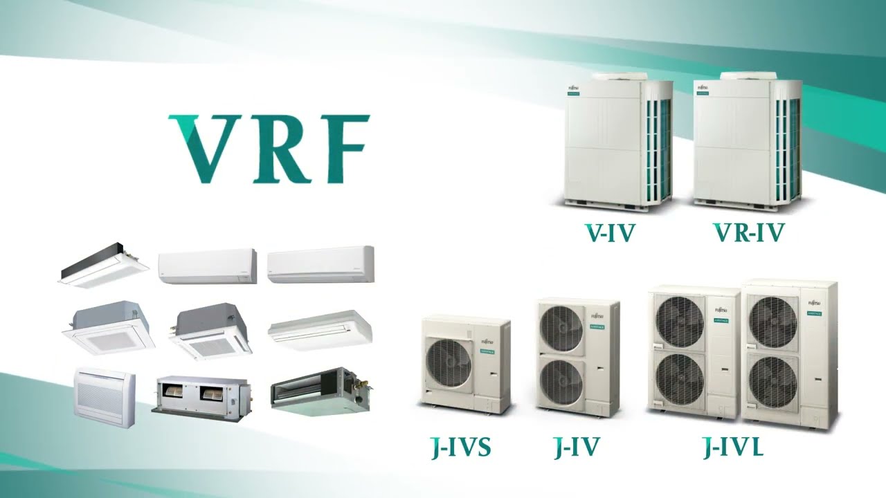
AIRSTAGE VRF Systems Common Features
![]() 08:38
08:38
Features
Outdoor system lineup
Greater energy efficiency
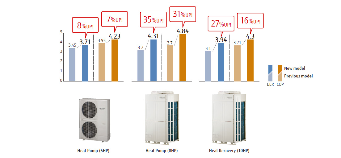
Significantly greater efficiency is achieved by the use of a DC twin-rotary compressor, inverter technology, and a large heat exchanger.
Energy-saving Features
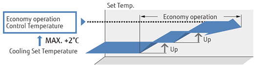
Economy mode
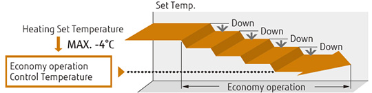
Economy mode can be set by a remote controller. The previously set temperature is overridden step by step automatically over time.
Setting temperature range limitation
Sets the minimum and maximum limits on room temperature to establish an optimum balance between energy-saving performance and comfortable environment.
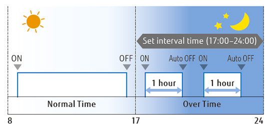
Auto-off timer
- The indoor unit turns itself off when a specified length of time has elapsed after the timer is activated.
- A desired time frame can be specified for the Auto-off timer.
Capacity saving mode
Operation capacity can be reduced in 5 steps from the rated capacity. This mode cuts down on peak power consumption and eases the maximum load on the unit.
Better comfort
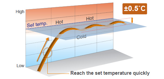
Precise control of refrigerant flow
The combination of DC inverter control and individual control of electronic expansion valves of an indoor unit enables the precise and smooth control of the refrigerant flow. The benefit is the ability to set the room temperature up or down in 0.5°C increments.
Auto changeover
The air conditioner switches between the cooling and heating modes automatically according to the set temperature and the room temperature.
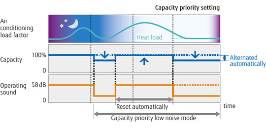
Quiet operation
Two low noise modes can be switched automatically between the one in which low noise is prioritized over performance and the other in which performance is prioritized over low noise, depending on the room temperature and outdoor temperature. This feature can be controlled by an external input from the outdoor unit or a system controller.
Design flexibility
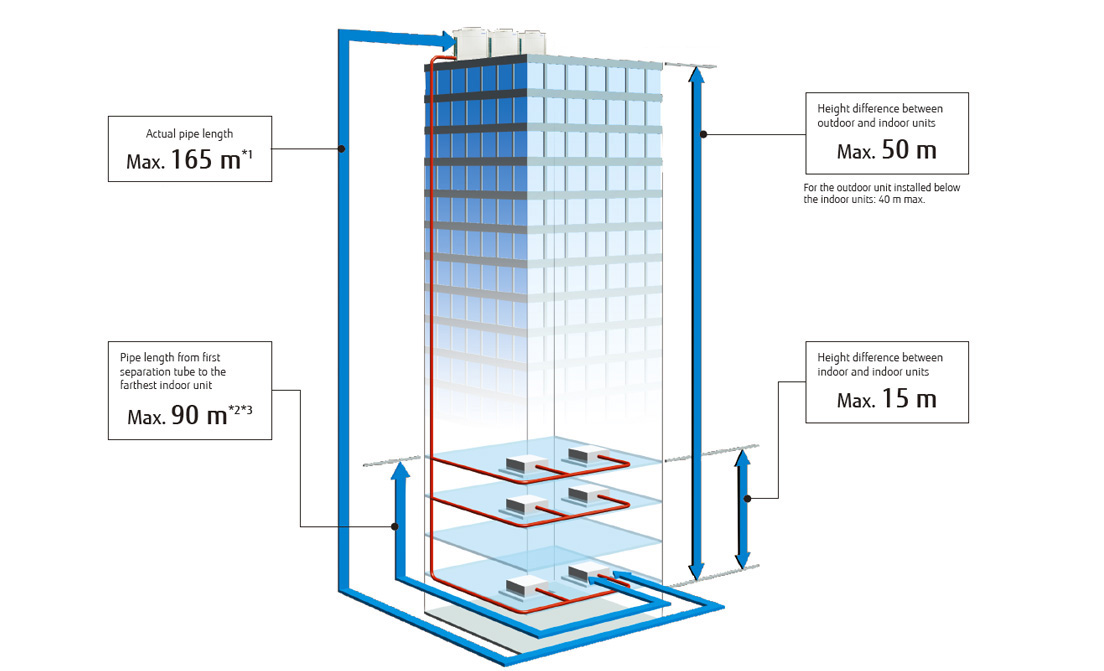
Max. allowable piping length: 1,000 m
AIRSTAGE V-III Series and V-II Series
The best-in-class maximum allowable piping length of 1,000 m increases flexibility of installation in a variety of buildings.
- *1.
- The maximum piping length for the VR-II, V-III, and V-II Series is 150 m.
- *2.
- For the V-III Series, the piping length between the nearest indoor unit and the farthest indoor unit, originating from the first separation tube, must be 60 m or less.
- *3.
- A maximum of 60 m for the VR-II and V-II Series
High static pressure
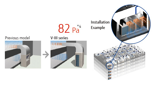
A condenser hood can be connected to the outdoor unit to achieve a standard static pressure of 82 Pa*4. This allows the outdoor unit to be installed in an equipment room in a high-rise building.
The use of a large diameter fan and a DC motor achieves an external static pressure of 82 Pa*4. This is approximately 2.6 times greater than the previous-generation model.
- *4.
- 80 Pa for the V-III, VR-II, and V-II series.
High reliability
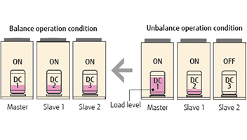
Life-extending operation*1
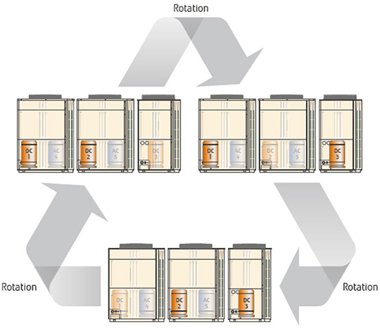
Compressors are set to start operating in rotational order to equalize the cumulative running time of each unit.
- *1.
- The start and stop timings are alternated among connected compressors.
Protection against liquid flowback
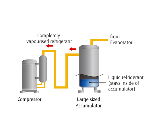
A large accumulator captures not-yet vaporized refrigerant to prevent liquid refrigerant from being fed into the compressor.
Blue fin heat exchanger
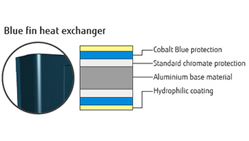
The corrosion-resistant blue fin treatment is applied to the heat exchanger of the outdoor unit.
Backup operation
If one compressor fails, the remaining compressors will initiate backup operation*2.
- *2.
- Backup operation may not work for all types of failures.
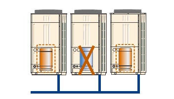
Advanced refrigerant control*3
A compressor control logic controls the inverter speed to balance the mass airflow rate of refrigerant in each outdoor unit.
- *3.
- Not available for the AIRSTAGE J-III or J-IIS Series
Easy installation
Great transportability
- A lifting strap can be hooked to an outdoor unit for use with a crane.
- The outdoor unit can be lifted and transported by forklift.
- It fits into a small elevator.
Easy access
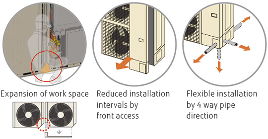
The removable L-shaped front panel provides more room for installation and service work.
Multiple installations can be performed easily and efficiently even in tight spaces.
Simplified wiring work
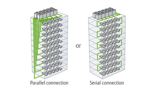
Maximum allowable wiring length: 3,600 m
The communication wiring can be installed seamlessly among the indoor, outdoor, and RB Units, which makes the installation of the wiring system easier.
* The automatic address setting is not available on a serially connected multiple refrigerant system.
Automatic address setting
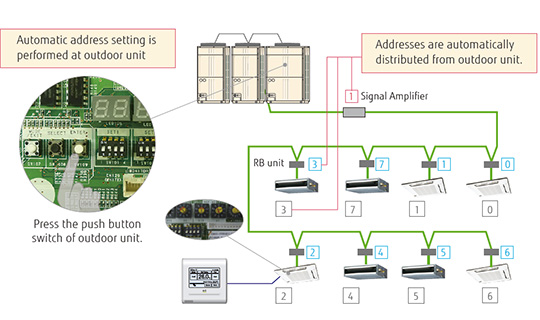
Addresses of connected indoor units, RB Units, and Signal Amplifier can all be set automatically from the PCB in the outdoor unit.
Addresses can be set manually from an indoor unit or a remote controller.
Easy service and maintenance
- Movable PCB panel
- Enables easier access behind the PCB for maintenance work.
- Easy-to-read 7-segment LED
- Shows the following operation and error status without using any special tool:
- System operation mode
- Discharge temperature and pressure
- Compressor operation status
- Address, error code, and the number of errors of an indoor unit in trouble
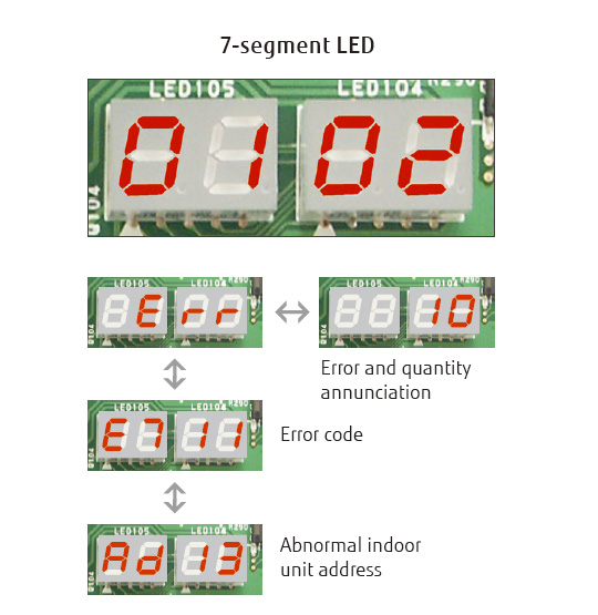
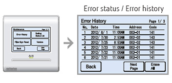
The error status can be checked on an outdoor unit's display.
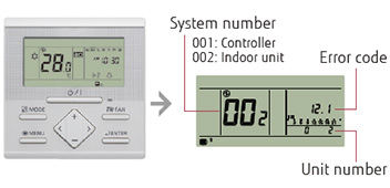
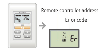
The error status can be checked via a Wired Remote Controller for indoor units.
An error code is displayed on an LCD screen.
Wired Remote Controller
Simple Remote Controller
Wired Remote Controller with touch panel
Error diagnosis by the Service Tool software
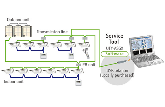
Connection to the Service Tool software
- A detailed operation status and recent error history can be checked and analyzed with Service Tool.
- The last 5 minutes of operation status can be saved continuously.
Remote monitoring
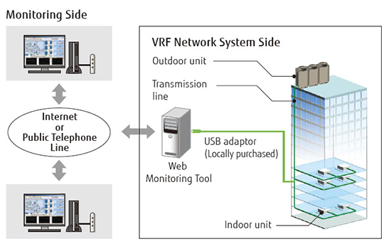
The Web Monitoring System enables the monitoring of the system's operation status at any time via the Internet to ensure trouble-free operation.
The VRF network system operating in a building can be monitored in real time via the Internet.